


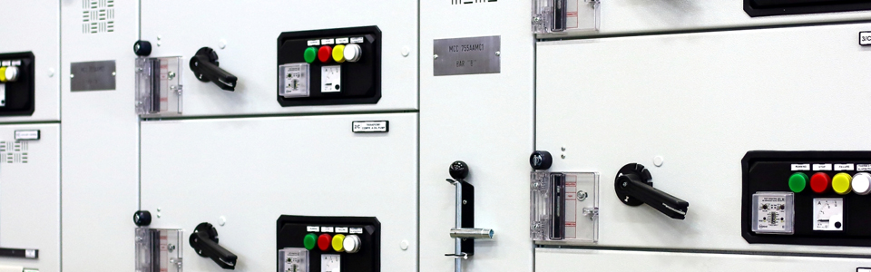

MOTOR CONTROL CENTER
The Motor Control Center is an ideal switchboard for the command and protection of electrical motors.
The drawers allow any type of use. Each column can have up to 10 drawers. The module drawers range from 200 mm increasing by 100mm up to 800 mm. The removable drawers allows rapid substitution with the board in function. All the drawers of equal size are exchangeable between them for maximum flexibility and continuity of the equipment function.

With the door closed the drawer can take any of the following positions:
- Draw-out (power grips and auxiliary connector isolated)
- Test (power grips isolated and auxiliary connecter inserted)
- Draw-in (power grips and auxiliary connector inserted)

Inside the compartment, with the drawer removed IP 2X protection is guaranteed by use of automatic shutters made of isolating material which segregate the voltage parts.
It is possible to connect cables up to a section of 120 mm2 to the power connector. Use of mechanical interlocks inhibits sectioned of the drawer when loaded. The size of the drawer is determined on the basis of the type of use and on the components necessary for the proper functioning of the motor.
Each column is equipped with a side compartment for connection of the power cables and auxiliary. The compartments are equipped with special supports that facilitate cable fixing. The minimum width of these compartments is 210 mm, which can be increased in accordance with the needs of the customer. The cable entry can be done in the switchboard from the top or from the bottom. Accessibility to the board for any maintenance works is from the front.
ELECTRICAL SPECIFICATIONS
- Rated Voltage (Un): up to 1000 V
- Rated Current (In): up to 2500 A
- Current c.to c.to (Icw): up to 65 kA per 1 sec.
- Internal arch resistence: up to 65 kA per 0,3 sec.
Size mm (LxHxP) 850/940x2250x500

REMOVABLE DRAWER
The drawer can be used for various types of motor starting with the possibility to install components of main constructors.
Each drawer includes:
- 3/6 entrance power clamps
- 1 earth clamp
- 1 auxiliary connector
- 1 support of commands and signage
- 3/6 exit power clamps

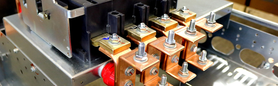
POWER CONNECTORS
Power clamps are built on two semi-clamps, which are to be inserted in a C shaped profile. In the event of a short circuit, the electrodynamics force induces the two semi-clamps to increase the contact pressure with a vertical profile, in this way voltage performance during a breakdown is improved.
Each clamp has a 250A voltage and the possibility to reach 500 A by install a second clamp in parallel.

AUXILIARY CONNECTOR
The auxiliary connector is self-centering and it is made of two resin monoblocks, which contain 32 sliding contacts having a rated current of 12 A. Special devices guarantee continuity of contact even during vibration.

POWER CENTER
The Power Center is distribution switchgear developed for installation in electrical systems with high power and in the presence of considerable short-circuit currents.
This type of equipment must guarantee maximum safety to employees, continuity of service and easy inspection and maintenance.
Power Center fully meets these requirements.
Built in press formed metal sheet resistant to the electrodynamics forces generated by failure currents and to overloads due to the internal arch up to 100 kA. The structure is designed in such way that it allows access to the board from both the front as well as the back for maximum safety of the operator.


From the front you can access to the auxiliary and power components, always with the degree of protection IP 2X, even when the doors open

From the rear, you can access to the zone cables, to bus bars derivation properly segregated and to the auxiliary terminal… The switchboard is built with 4B segregation or lower depending on the equipment requirements. The main bus bars system is placed at the top of the switchboard.

SPECIAL FEATURES
It is possible to place MCC Columns with removable drawers within the Power Center for more flexible use and to thus create a Power Motor Control Center board.

For major safety of the operator, the Power Center can be made to resistance internal arc for a fault current up to 65 kA for 0.3 sec.
ELECTRICAL SPECIFICATIONS
- Rated Voltage (Un): up to 1000 V
- Rated Current (In): up to 5000 A
- Current c.to c.to (Icw): up to 100 kA per 1 sec.
- Internal arc resistance: up to 65 kA per 0,3 sec.
The switchboard is in full compliance to standard IEC 61439-1 and 61439-2.

BUS-BARS SYSTEM
The bus bars of the system consists of electrolytic copper plates of various sections according to the current requirements. The horizontal bars are placed in the top of the switchboards and are sustained by small steel bars and comb-type isolator in PBT made by Alfaquadri.
The bus bars consist of pieces bolted together run through the entire length of the switchboard. From these, by means of bolted joints, are derived the vertical bars at the rear of each compartment from which in turn are derived with special joints bolted feeds of individual users.
Vertical posts in the back of each compartment derive from the horizontal bus bars by means of bolted joints.
Vertical posts in the back of each compartment derive from the horizontal bus bars by means of bolted joints.

CABLE COMPARTMENTS
The cable compartments are placed at the lower end of the switchboard and segregated from each other and from the other parts with the voltage, respecting the 4B construction form. After opening the rear door can be accessed to the cable compartment where are placed the auxiliary terminal fixed to the structure of the switchboard.
Each functional unit has its own cubicle for power cables, arranged by copper bars to connect the cables and closed by a plate that allows the accessibility to the board, even in service, ensuring operator safety.
EQUIPMENT LAYOUT
Power as well as auxiliary equipment is placed at the front of the board. The cubicles allow access to the components at any time. The components are placed in such way that maintenance can be carried out without removing the other parts of the board. The components mainly offer degree of protection IP 2X. When this is not possible, the safety of the operator is guaranteed by use of mechanical blocks or isolation using isolating material.
